

Side Panel Inner Inspection Fixture for Automotive Body Components
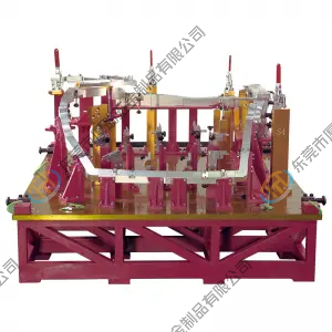
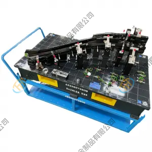
This side panel inner inspection fixture is a dedicated tooling solution for automotive sheet metal component inspection. The project features multiple vertically arranged fixture units mounted on mobile platforms, providing an organized configuration for handling and positioning inspection equipment within a manufacturing environment.
The fixture assembly shown in the project incorporates structural supports, bolted mounting plates and adjustable mechanical elements. Its configuration is intended to support component-specific inspection requirements, with the final locating arrangement and checking points determined by the approved engineering design.
For automotive body manufacturing projects, dedicated inspection tooling helps establish a consistent reference condition for evaluating component geometry and dimensional characteristics.
Project-Specific Fixture Configuration
The fixture configuration is developed around the requirements of the target component rather than a universal inspection layout.
Key design considerations include:
- Structural arrangement: Vertical support members and mounting plates provide the framework for the individual fixture units.
- Component positioning: Locating and supporting elements are arranged according to the component’s approved datum structure.
- Mechanical adjustment: Appropriate adjustable elements allow the fixture configuration to accommodate its specified positioning and inspection requirements.
- Equipment handling: Mobile platforms facilitate the movement of the fixture assembly within the designated work area, subject to the facility’s handling procedures.
- Inspection accessibility: The fixture layout should provide access to the specified checking points and measurement locations.
The final inspection capability depends on the approved fixture design, the component drawing and the measurement procedure.
Engineering Considerations for Side Panel Inner Components
Automotive side panel inner components can include formed surfaces, mounting features, holes and interfaces that must align with adjacent body structures.
An inspection fixture for this type of component should account for the geometry of the part and the functional importance of its reference features.
The engineering team should establish the datum scheme, define the required inspection points and determine suitable support and locating positions before finalizing the fixture structure.
Clamping forces must also be considered carefully because excessive restraint can distort thin sheet metal components and affect measurement results.
Where dimensional verification is required, the inspection method should be selected according to the relevant tolerances, accessibility and customer acceptance criteria.
Integration With Automotive Tooling Projects
Inspection fixtures are one element of a broader automotive manufacturing system. Their design requirements are influenced by the component-forming process, assembly interfaces and downstream quality requirements.
For related manufacturing capabilities, explore TTM Group’s automotive tooling and manufacturing solutions.
For applications involving electronically supported contour measurement, see the Electronic Contour Checking Fixture solution.
Customized Inspection Fixture Development
Each inspection fixture project should be evaluated against its own component geometry, dimensional requirements and operating conditions.
To discuss a similar project, manufacturers can prepare the component CAD model, 2D engineering drawings, GD&T requirements, critical inspection characteristics and expected inspection method.
These inputs help the engineering team assess the fixture layout and determine an appropriate solution for the intended application.
Contact TTM Group to discuss customized automotive tooling requirements and related manufacturing capabilities.

.png)
.png)