
With the rapid development of the automobile industry, people have higher and higher requirements for the practicability, reliability and aesthetics of automobile panels. Drawing I-shaped is the most critical process in the forming process of body panels. Whether its design is reasonable will determine It directly affects the appearance quality of automobile panels and the development cycle of new models. Therefore, TTM analyzes the drawing process of automobile panels, which is beneficial to shorten the mold design time, improve the appearance quality of panels, and thus improve the competitiveness of enterprises. This paper mainly introduces the drawing process of the side wall outer panel.
1.1 Commonly used materials for side panels
The forming process of the outer panel of the side wall is generally 4-5 steps (excluding blanking). In order to ensure the quality of the noodle product and reduce the difficulty of debugging, most of the side walls are currently completed in five steps. Due to the complex shape of the side wall and the deep drawing depth, the commonly used sheet materials are DC56D+Z or DCO7E+Z+pre-phosphating with better mechanical properties, and the material thickness is generally 0.65mm, 0.7mm, and 0.8mm. Considering the rust prevention and the rigidity and formability of the parts, the preferred material is DCDC56D+Z/0.7t. At the same time, the boundary cracking of the side door opening has a great relationship with the R angle of the bad material line. The smaller the R angle of the bad material at the door opening, the easier the boundary is to crack.
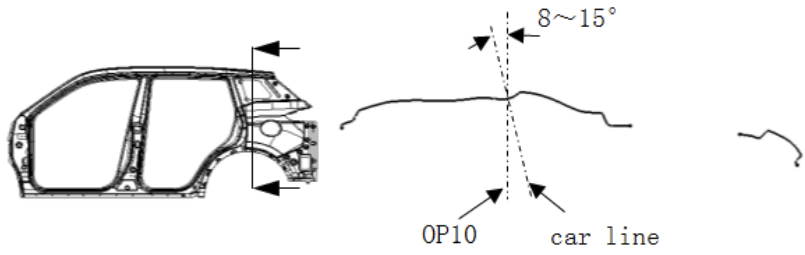
1.2 Stamping direction of side wall outer panel
Comprehensively considering the drawing forming process of the side wall outer panel, generally the stamping direction of the side wall outer panel is at an angle of 8-15° with the Y direction of the vehicle body.
1.3 Supplementary points for attention in side wall outer panel process
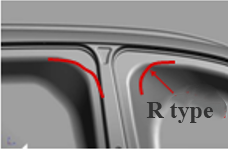
1.3.1 Attention points for setting the supplementary shape of the upper part of the B-pillar
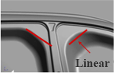
There are two setting methods for drawing the remaining meat at the upper corner of the B-pillar. One is to draw the parting line of the punch at the corner of the punch close to the product shape, that is, the R type. This shape of the remaining meat can reduce the position of the upper corner. The thickness and thinning rate of the material can be adjusted to prevent cracking. The other is to set the parting line of the punch at the corner of the drawing punch to a linear shape, that is, a straight line. This shape of the remaining meat can improve the formability of the upper corner and stop The surface of the upper part of the B-pillar is deformed.
1.3.2 Points for attention in setting the supplementary shape of the process at the position of the door opening
The parting line at the door opening should change linearly as much as possible, and the transition should not be sharp or turn
1.4 Setting of drawbeads on side wall outer panels
Due to the complex shape of the side wall, in order to effectively control the flow of materials in each part, double ribs are generally used. In order to prevent the drawbead from crawling into the product surface and affecting the appearance quality of the product, the distance between the drawbead and the product near the threshold should be widened, and then the position of the drawbead should be adjusted by CAE simulation analysis using Autoform software. The drawbead in the door opening should be as smooth as possible, and the R angle should be as large as possible.
Post time: May-24-2023

.png)
.png)